How to Rivet Aluminum?
A rivet is a permanent mechanical fastener. Before being installed a rivet consists of a smooth cylindrical shaft with a head on one end. The end opposite the head is called the buck-tail. On installation the rivet is placed in a punched or pre-drilled hole, and the tail is upset, or bucked (i.e. deformed), so that it expands to about 1.5 times the original shaft diameter, holding the rivet in place. To distinguish between the two ends of the rivet, the original head is called the factory head and the deformed end is called the shop head or buck-tail.
 A rivet is a permanent mechanical fastener.
Because there is effectively a head on each end of an installed rivet, it can support tension loads (loads parallel to the axis of the shaft); however, it is much more capable of supporting shear loads (loads perpendicular to the axis of the shaft). Bolts and screws are better suited for tension applications.
Fastenings used in traditional wooden boat building, like copper nails and clinch bolts, work on the same principle as the rivet but were in use long before the term rivet came about and, where they are remembered, are usually classified among the nails and bolts respectively.
There are a number of types of rivets, designed to meet different cost, accessibility, and strength requirements:
Solid rivets
Solid rivets are one of the oldest and most reliable types of fasteners, having been found in archaeological findings dating back to the Bronze Age. Solid rivets consist simply of a shaft and head which are deformed with a hammer or rivet gun. The use of a rivet compression or crimping tool can also be used to deform this type of rivet; this tool is mainly used on rivets close to the edge of the fastened material, since the tool is limited by the depth of its frame. A rivet compression tool does not require two people and is generally the most foolproof way to install solid rivets.
 Three aluminium blind rivets: 1/8″, 3/32″, and 1/16″
Solid rivets are used in applications where reliability and safety count. A typical application for solid rivets can be found within the structural parts of aircraft. Hundreds of thousands of solid rivets are used to assemble the frame of a modern aircraft. Such rivets come with rounded (universal) or 100° countersunk heads. Typical materials for aircraft rivets are aluminium alloys (2017, 2024, 2117, 7050, 5056, 55000, V-65), titanium, and nickel-based alloys (e.g. Monel). Some aluminum alloy rivets are too hard to buck and must be softened by annealing prior to being bucked. “Ice box” aluminum alloy rivets harden with age, and must likewise be annealed and then kept at sub-freezing temperatures (hence the name “ice box”) to slow the age-hardening process. Steel rivets can be found in static structures such as bridges, cranes, and building frames.
Aircraft raw materials come in different but limited sizes due to manufacturing limitations as well as economical distribution. The designer has to choose materials which are available, can be transported to the manufacturing facility (even the homebuilder’s basement or garage), can be cut to required sizes with the minimum tools, and can be handled without causing too many rejects due to mishandling … and still end up with an aircraft of appreciable size, adequate strength and good looks.
Aircraft can’t just be made out of one big sheet of material and “wrapped together.” Rather, various parts have to be formed out of different types of material and joined together. Each of those parts carries a load and the fastener that brings these parts together has to carry the load from one part to the other. If we have, for example, 1,000 lbs. to be carried over from one skin to another, we can choose various ways of achieving this (see figure 1).

The designer of an aircraft chooses the solutions best adapted to the materials used - a continuous joint with wood and composites, a single bolt or heavy (thick) fittings with steel; or riveted joints on relatively light gauge materials and/or when the joints are long (to avoid the weight penalty of many steel bolts).
For over 50 years, riveted aluminum structures have been very successful, and are found to varying degrees on virtually all aircraft (whether the complete airframe or just an instrument panel). They do not fail under static or repeated loads and they do not corrode if the rivets are well chosen and properly set.
How to set the rivets correctly can be learned quite easily and should be explained by the designer when he sells drawings or kits to build an aluminum aircraft. The choice of rivets is very simple: only 2017 alloy rivets are commercially readily available (these are the “AD” rivets mentioned in earlier columns). They have good corrosion resistance and are compatible with 2024 and 6061 materials. Now, let’s look at why they are also a good structural fastener. (See figure 2). First the hole is drilled slightly oversized (via the use of number drills) so that the rivet can easily be introduced after deburring (see Figure 2, item E).
Note that the drawing also indicates correct rivet size depending on the total metal thickness, called the “grip’. Then the rivet is squeezed (compression is achieved by a rivet ‘gun” and a “bucking bar”. The pneumatic gun hammers on one side while the bucking bar, which is simply a heavy chunk of steel, provides the reaction on the other.)

When the rivet shank is compressed, its diameter grows until the hole is completely filled. (See Figure 2, item F). When we further compress the rivet it can only grow further outside the hole and thus the formed head is shaped (see Figure 2, item G), which also gives a correct formed head dimension. Note that a visual inspection of the rivet will immediately tell you if the rivet is good or if it has to be drilled out and replaced.
First, AD rivets are manufactured with adequate quality control which guarantees you the correct alloy (when you mix bonding cement or resins. you are responsible!)
- The rivet fills the hole completely so that no relative motion is possible.
- The original as well as the formed head both rest both very well an the parts having been compressed into place. This makes for a snug and sealed joint which will prevent any water from creeping under the heads and corroding underneath.
Also very important is the fact that the heads squeeze assembled parts tightly together and when the loads are applied (see arrows on Figure 2), part of the load is transmitted from one sheet to the other by friction. It just happens in aircraft (this is not the case with racing cars) that the part of the load transmitted by friction corresponds to the high frequency engine loads which would otherwise fatigue the rivet (or require an overdesign of the rivet joint which is done in racing cars where the engine vibration loads are much larger with respect to the static loads).
As mentioned, solid riveting when correctly done is an excellent fastener - both reliable and durable. But it also has some drawbacks:
- You need special equipment (you’ll need to buy an air compressor, rivet gun(s), rivet snaps and bucking bars).
- You need some expertise and prior practice (you’ll need a good teacher for this - errors can be costly in more ways than one);
- You need access to both sides of the parts to be assembled (and this is obviously not always easy or possible: How will you get the bucking bar inside an aileron of a small aircraft?). You’ll often need a helper to “buck” the rivet on the other side, or have long skinny arms and/or a full assortment of bucking bars.
High strength structural steel rivets
Until relatively recently, structural steel connections were either welded or riveted. High-strength bolts have completely replaced structural steel rivets. Indeed, the latest steel construction specifications published by AISC (the 13th Edition) no longer covers their installation. The reason for the change is primarily due to the expense of skilled workers required to install high strength structural steel rivets. Whereas two relatively unskilled workers can install and tighten high strength bolts, it took a minimum of four highly skilled riveters to install rivets in one joint at a time.
At a central location near the areas being riveted, a furnace was set up. Rivets were placed in the furnace and heated to a glowing hot temperature, at which time the furnace operator would use tongs to individually remove and throw them to catchers stationed near the joints to be riveted. The catcher would place the glowing hot rivet into the hole to be riveted, and quickly turn around to await the next rivet. One worker would then hold a heavy rivet set, also called a ‘dolly’ against the round head of the rivet, while the hammerer would apply a pneumatic rivet hammer to the unformed head, causing it to mushroom tightly against the joint in its final domed shape. Upon cooling, the rivet would contract and exert further force tightening the joint. This process was repeated for each rivet.
Such riveted structures may be insufficient to resist seismic loading from earthquakes if the structure was not engineered for such forces, a common problem of older steel bridges. This is due to the fact that a hot rivet cannot be properly heat treated to add strength and hardness. In the seismic retrofit of such structures it is common practice to remove critical rivets with an oxygen torch, precision ream the hole, and then insert a machined and heat treated bolt.
Semi-tubular rivets
Semi-tubular rivets (also known as tubular rivets) are similar to solid rivets, except they have a partial hole (opposite the head) at the tip. The purpose of this hole is to reduce the amount of force needed for application by rolling the tubular portion outward. The force needed to apply a semitubular rivet is about 1/4 of the amount needed to apply a solid rivet. Tubular rivets can also be used as pivot points (a joint where movement is preferred) since the swelling of the rivet is only at the tail. Solid rivets expand radially and generally fill the hole limiting movement. The type of equipment used to apply semi-tubular rivets range from prototyping tools (less than $50) to fully automated systems.
Typical installation tools (from lowest to highest price) are hand set, manual squeezer, pneumatic squeezer, kick press, impact riveter, and finally PLC-controlled robotics. The most common machine is the impact riveter and the most common use of semitubular rivets is in lighting, brakes, ladders, binders, HVAC duct work, mechanical products, and electronics. They are offered from 1/16-inch (1.6 mm) to 3/8-inch (9.5 mm) in diameter (other sizes are considered highly special) and can be up to 8 inches (203 mm) long. A wide variety of materials and platings are available, most common base metals are steel, brass, copper, stainless, aluminum and most common platings are zinc, nickel, brass, tin. All tubular rivets are waxed to facilitate proper assembly. The finished look of a tubular rivet will have a head on one side, with a rolled over and exposed shallow blind hole on the other. Semi-tubular rivets are the fastest way to rivet in mass production but require a capital investment.
Blind rivets
Blind rivets, also known as pop rivets, are tubular and are supplied with a mandrel through the center. The rivet assembly is inserted into a hole drilled through the parts to be joined and a specially designed tool is used to draw the mandrel into the rivet. This expands the blind end of the rivet and then the mandrel snaps off. These types of blind rivets have non-locking mandrels and are avoided for critical structural joints because the mandrels may fall out, due to vibration or other reasons, leaving a hollow rivet that will have a significantly lower load carrying capability than solid rivets. Furthermore, because of the mandrel they are more prone to failure from corrosion and vibration. Unlike solid rivets, blind rivets can be inserted and fully installed in a joint from only one side of a part or structure, “blind” to the opposite side.
Prior to the adoption of blind rivets, installation of a solid rivet typically required access to both sides of the assembly: a rivet hammer on one side and a bucking bar on the other side. Seeking an alternative, inventors such as Carl Cherry and Lou Huck experimented with other techniques for expanding solid rivets. The blind rivet was developed by the United Shoe Machinery Corporation.
Due to this feature, blind rivets are mainly used when access to the joint is only available from one side. The rivet is placed in a pre-drilled hole and is set by pulling the mandrel head into the rivet body, expanding the rivet body and causing it to flare against the reverse side. As the head of the mandrel reaches the face of the blind side material, the pulling force is resisted, and at a predetermined force, the mandrel will snap at its break point, also called “Blind Setting”.
A tight joint formed by the rivet body remains, the head of the mandrel remains encapsulated at the blind side, although variations of this are available, and the mandrel stem is ejected. They are available in flat head, countersunk head, and modified flush head with standard diameters of 1/8, 5/32 and 3/16 inch. Blind rivets are made from soft aluminum alloy, steel (including stainless steel), copper, and Monel.


 Alloy Suppliers
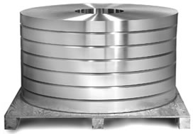
  Aluminum
  Aluminum Extrusions
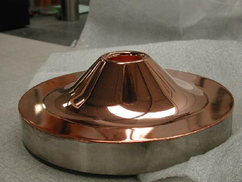
  Copper-Brass-Bronze
  Nickel
  Magnets
  Stainless Steel
  Stainless Steel Tubing
  Steel Service Centers
  Titanium
  Tungsten
  Wire Rope