Introduction:
An 8″ x 6″, 316L stainless steel reducer was sent for failure analysis (Fig 1). It had been in service for 13 months when a leak was noticed. The reducer was installed on acid storage tank, equipment number 50-200. The anodically protected carbon steel tank, contained off specification concentrated 93% sulphuric acid. The flow rate through the reducer was 400 gal/min.
 Figure 1. Photograph of reducer
The tank was originally designed with a 4″ diameter carbon steel nozzle, at floor level, that connected directly to a valve (Fig 2). This lasted seven to eight years without incident. The design was changed to accommodate renovations so that an 8″ carbon steel nozzle was installed 6″ above the tank floor.
 Figure 2. Old tank installation
 Figure 3. Tank installation at the time of reducer failure.
This nozzle lead into the failed reducer, which then connected to a valve composed of alloy 1-0 steel (Fig 3). This valve was said to be badly corroded. The valve then led to a 6″ pipe made of 316L stainless steel in which no problems were found. After the reducer failure, the piping arrangements were changed so that the reducer is now after the valve.
Observations:
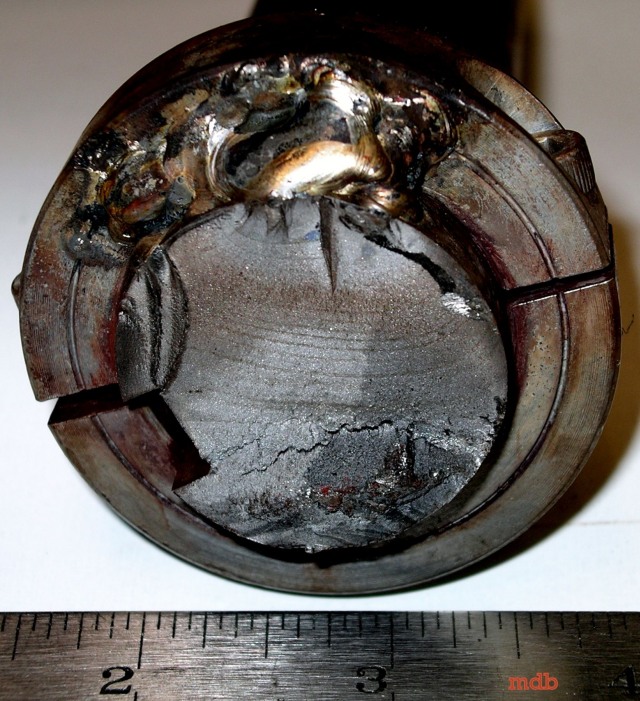
Visual examination of the reducer revealed an area at the top where little damage was observed (Fig 4). This area, which was probably an air pocket, extended from the top of the 87′ diameter flange into the reducing pipe where is stopped just before the 6″ diameter flange. Damage in this area consisted of minor pitting (Fig 5).
 Figure 4. Photograph of the top insider of the reducer showing the area at the top where little damage occurred
 Figure 5. Microphotograph of pitting in air pocket. 15X
Figure 6. Photographs showing areas to the (a-left) right and (bright) left of the top relatively undamaged surface. The red arrow in (a) indicated where the leak occurred
 Figure 7. Photograph taken on the outside of the reducer showing the hole where the reducer leaked
Damage, resembling a honeycomb structure in places, was most severe just below the air pocket in the reducing pipe near the 6″ diameter end (Fig 6). This is where the leak was found (Fig 7). The damage becomes less severe in the pipe section towards the bottom. Only pitting was found in both the 8″ and 6″ flanges.

Figure 8. SEM photograph of the inside surface of the reducer in the damaged area. 200X
 Figure 9. SEM photograph of the inside surface of the reducer in the damaged area. 500X
Closer examination of the inside surface of the reducer with a SEM revealed dimples (Fig 8). These features are typical of a ductile deformation, which indicates abrasion. The orientation of the features also follows the direction of liquid flow. Pitting and uniform corrosion was also found in the region (Fig 9).
 Tabel 1 Result of chemical analysis
Chemical analysis of the flange and the pipe revealed that they both conform to AISI-SAE standards for 316L stainless steel (Table 1).
Conclusions and Recommendations :
A combination of two mechanisms caused the failure. Severe turbulence in the reducer caused a degradation of the passive layer that protects the stainless steel from corrosion. This would have left the system open to severe corrosion, which in turn would have lead to failure. The top of the reducer was probably protected by the presence of an air pocket.
The second mechanism was erosion, originating when air bubbles near the surface imploded causing mechanical damage, cavitation. Turbulence in the system may have formed bubbles from the air pocket at the top of the reducer. These bubbles would then have been carried into the reducer where increasing pressures would have caused them to implode. The highly corrosive environment would have increased the rate of degradation dramatically.
You might also like
 |
 |
 |
 |
 Alloy Suppliers
 Aluminum
 Aluminum Extrusions
 Copper-Brass-Bronze
 Nickel
 Magnets
 Stainless Steel
 Stainless Steel Tubing
 Steel Service Centers
 Titanium
 Tungsten
 Wire Rope